|
P r o d u c t s |
|
|
FC Controller Components |
|
|
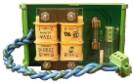
110-Volt
/ 220-Volt Power Supply Board
- Supplies 12V AC to the regulator on the Data-Acquisition board. Note: See Installation Instructions for 220-Volt
operation.
Figure 1 Power Supply Board
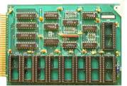
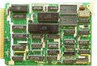
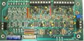
Programmable
DAQT Board - Holds the firmware
that determines the functions of the Data Acquisition System.
Figure 2 Data-Acquisition Temperature Board Bulb
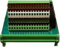
Connection Board - Allows
connection of digital devices. Normally Digital Temperature Sensors.
Figure 3 Digital Connection Board
Eprom Card
- Six 64k EPROM chips witch hold the main program that runs the kiln. The card comes pre loaded with a program
and can only be changed if sent into Frank Controls Ltd. It is the brains behind the operation of
the kiln.
Figure 6 Eprom Card SIO
Card - Converts parallel
data from the STD bus to serial data.
The ports the Frank Control Computer System uses to talk with the PC
and PLC.
Figure 7 SIO Card CPU
Card - The Motherboard
that controls all the other cards.
Runs the program in the Eprom Card.
Figure 8 CPU Card Power
Fail Card - Monitors the
power line. If the Frank Control Computer System has power the
LED will glow red. If there is a loss
of power or the card is not working, the LED will go out. Only the top of the two connectors is used
for normal operation.
Figure 9 Power Fail Card
Battery Back-Up Card - Holds the RAM that the Frank Control Computer System uses. A real time clock chip allows the computer
to keep track of time. Contains a
battery to hold memory in the RAM on a power failure so the data in the RAM is not lost. There is also an on board charger for the
(3v) NICAD battery.
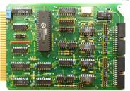
Figure 10 Battery Back-Up Card DIGT
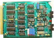
Card - 8085 microprocessor controlled onboard 8KB EPROM
& 2K RAM. This card holds the
program for communicating to the Data-Acquisition boards. It is connected to the Isolation board
through a 14-pin bus cable.
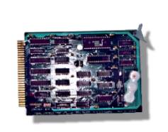
Figure 11 Digital Temperature Card DAC
Board - Converts serial data
from the DAQT board to eight 4-20mA analog output channels.
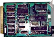
Figure 12 Digital to Analog Board Isolation Board
- Optically isolates the
Digital Temperature card from the Data-Acquisition Temperature System. This
board has six optically isolated Digital I/Os and one non-isolated
channel. The isolated channels
connect to the Digital Temperature System.
The non-isolated channel connects to the outside Digital Bulb. The 14-pin bus cable connects to the
Digital Temperature Card. It is
powered by 12 VDC from the Hammond 166F6 transformer.
Figure 13 Isolation Board ATX
Power Supply - Supplies
power to the Card Cage. See Appendix
for details on connections. Hammond
166F16 - Supplies 12v
power to the Isolation board and AC to J4 on the PFA card. |